


PCENERSYS BOLG
Beyond Textbook GFM: Designing Droop Control That Actually Survives the Field
Introduction
In the development of modern microgrids and emergency backup power systems, the "black start" capability of Battery Energy Storage Systems (BESS) has emerged as a key metric for assessing system resilience. When the main grid fails, the BESS must independently initiate a system startup within a "dead grid" environment (zero-voltage state) and establish a stable local voltage.
However, this is far more than a simple switching operation. During the transition from grid-tied to off-grid mode—and within the microsecond-scale window of system power-up and initialization—there must be absolute synchronization between the tolerance limits of high-voltage hardware and the microsecond-level precision of software control timing. Even a deviation of just a few milliseconds or microseconds in the control sequence can trigger severe electrical transient faults.
About the Author: A seasoned energy storage system integration engineer and BMS firmware development expert with extensive experience in the new energy industry. Throughout my career, I have led or participated in the on-site commissioning and system integration of global commercial, industrial, and utility-scale energy storage projects totaling over 500 MWh. In this blog post, drawing on hard-won lessons from the field, I will analyze a typical case of pre-charge and switching failure. My goal is to help fellow engineers steer clear of the "fatal pitfalls" associated with high-voltage timing sequences during the design phase.
On-Site Commissioning Disaster: A Post-Mortem of a Failed 100kW BESS Black Start
When translating theory into practice, on-site commissioning serves as the ultimate litmus test for system design. The subject of this case study was an all-in-one, liquid-cooled commercial and industrial energy storage unit with a rated capacity of 100kW/215kWh. On the DC side, the system utilized a Lithium Iron Phosphate (LFP) battery cluster rated at 768V and 280Ah, while the associated Power Conversion System (PCS) featured DC bus support capacitors connected in parallel, totaling a massive 8,000µF in capacitance. This substantial capacitance set the stage for the subsequent failure.
The incident occurred during an on-site black start test following a simulated microgrid power outage. Commissioning personnel initiated the process by pressing the "System Auto-Start" button on the Energy Management System (EMS) control interface. Immediately, a dull yet violent metallic bursting sound erupted from within the High-Voltage Unit (BDU). Although the system's smoke sensors failed to trigger, the monitoring screens instantly went blank. Seconds later, backup power engaged, and the system reported a critical fault code indicating "DC-side Level 2 Overcurrent / Pre-charge Failure," marking the total failure of the black start attempt.
Following an emergency power-down and safe discharge, we conducted a post-mortem inspection of the high-voltage enclosure. The findings were startling: the 150A DC fast-acting fuse in the main DC circuit had completely blown and showed signs of carbonization; meanwhile, the contacts of the main positive DC contactor exhibited severe arc erosion, with visible pitting and weld-bonding on their surfaces.
This prompted us to reflect deeply: the integrated energy storage unit had performed almost flawlessly during pre-delivery, one-to-one static laboratory testing. Why, then, did its internal pre-charge circuit instantly fail—generating such massive inrush current—when deployed in a real-world environment to execute a BESS "black start" (grid-forming) operation?
Exploring the Physical Nature of Inrush Current and Capacitor Charging Calculations for Component Selection
To fundamentally resolve the issue of hardware damage during black start operations, we must return to first principles and analyze the physical nature of inrush current.
Before the system closes the circuit, the DC-link capacitor (8000 µF) of the Power Conversion System (PCS) is fully discharged (with zero voltage across its terminals). Due to the physical characteristics of capacitors, the voltage across them cannot change instantaneously; thus, the moment the contactor closes, the capacitor acts as a direct short circuit to ground (impedance Z ≈ 0). Without a dedicated precharge circuit to limit the current, the high voltage (hundreds of volts) from the battery cluster would be applied directly across a circuit with near-zero resistance, generating a destructive inrush current of tens of thousands of amperes—sufficient to instantly fuse the contactor contacts and cause the fuse to blow explosively.
To limit this current, the energy storage system must charge the capacitor gradually through a precharge resistor. This process follows the transient response of a classic first-order RC circuit. Here, we derive the capacitor charging formula step-by-step:
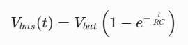
We now perform a quantitative verification using actual data from the case to reveal a critical flaw left by the original design team:
1. Hard-coding defect in the original design: The original system utilized a corrugated resistor with a resistance of 40 Ω and hard-coded a fixed pre-charge closing delay of 150 ms into the BMS firmware.Theoretical charging time calculation: The pre-charge time constant (τ) for the system is:

In accordance with safety standards for the power electronics industry, the main contactor is permitted to close only when the DC bus voltage (Vbus) reaches at least 95% of the battery's rated voltage (Vbat)—meaning the difference is less than 5%. This necessitates a charging duration of at least 3τ:

The devastating impact of insufficient charging: However, the original software timing forced the main contactor to close after only 150 ms of charging. At this point, the DC bus voltage, calculated using the capacitor charging formula, was merely:

At this point, there is a massive voltage difference of ΔV = 768V - 287.2V = 480.8V between the battery and the busbar. Assuming the total parasitic resistance of the high-voltage main circuit (including the resistance of conductors, fuses, etc.) is R_line = 0.05 Ω, the transient surge current generated at the moment of closing the switch is:
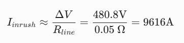
A massive current approaching 10,000 amperes instantly exceeded the melting integral (I²t) limit of the 150A fuse, causing the contactor contacts to instantly vaporize and fuse together.
Furthermore, the rated power (100W) of the pre-charge resistor represents a critical oversight. During a single pre-charge cycle, the energy stored in the capacitor is entirely absorbed by the pre-charge resistor in the form of heat:

Although a standard 100W wire-wound resistor may appear to have sufficient continuous power dissipation capability, the transient thermal capacity of its resistive wire and ceramic substrate is extremely low, rendering it unable to withstand a single pulse energy impact of up to 2359.3 J. After several unsuccessful self-start tests, the resistor experienced severe thermal drift due to intense heating; the resulting sharp spike in resistance further extended the actual charging time, ultimately accelerating the collapse of the entire control sequence.
Hardware Modification and Flawless BMS Control Sequence/Software State Machine Design
To thoroughly resolve electrical damage caused by inrush current, we must adopt a two-pronged approach: enhancing hardware resilience through physical modifications while simultaneously establishing a flawless control sequence at the software level.
Hardware Modification Plan
First, we are replacing the original 40Ω/100W resistor—which was highly susceptible to thermal drift—with a heavy-duty, gold-anodized aluminum-housed wire-wound resistor rated at 100Ω/200W. This resistor is specifically engineered for high-power transient absorption, offering a single-pulse energy capacity that safely exceeds 3000J.
Following this replacement, and based on our calculations, the pre-charge time constant increases accordingly due to the shift to a 100Ω resistance:

Theoretically, the safe closing time (3τ) is extended to 2.4 seconds. If a fixed time-delay control strategy were still used under these conditions, closing failures would likely occur due to fluctuations caused by external factors (such as changes in capacitor characteristics at low temperatures or increased line impedance).
Software Timing and Control Reconfiguration
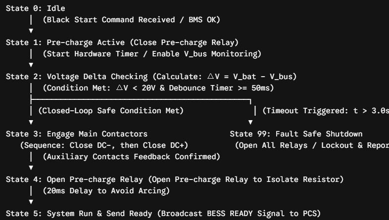
To address this, we completely abandoned the indiscriminate and high-risk "fixed time-delay closing" logic and reconfigured it into an adaptive BMS state machine control logic based on closed-loop feedback of the bus voltage difference. This timing control logic is illustrated in the control sequence diagram below:
AC-Side Control Handover: Seamless Transition from PLL to Droop Control
Once the DC-side pre-charge circuit has successfully closed and the BMS has issued a "Ready" signal, the energy storage cabinet's DC bus voltage is fully established. However, in a BESS black-start scenario, the real challenge is just beginning: the main grid is disconnected, leaving the local AC bus in an "islanded" state with zero voltage and zero frequency. The PCS must establish a stable three-phase AC voltage from scratch.
In conventional grid-connected operation, the converter employs Grid-Following (GFL) control. This mode relies heavily on a Phase-Locked Loop (PLL) to track the voltage vector and phase of the main grid in real-time, enabling current injection that is synchronized in both frequency and phase. However, during a black start—where the grid is absent—the lack of a voltage reference causes the PLL to lose lock, leading to severe control instability or frequent "PLL failure" alarms. At this point, Grid-Following control becomes completely ineffective.
To break this "chicken-and-egg" deadlock, the system must rapidly and seamlessly switch its control algorithm to Grid-Forming (GFM) control, incorporating droop control.
Under droop control, the PCS acts as an independent AC voltage source. The process of establishing the AC voltage is subject to extremely strict timing constraints. First, the PCS executes a voltage "Soft Start" sequence, ramping the output voltage slowly and smoothly from 0V to the rated 400V; this minimizes the inrush excitation current caused by the instantaneous magnetization of the local transformer.
Once the voltage is established, the PCS enters the droop regulation mode. By emulating the external characteristics of a synchronous generator and utilizing the bidirectional feedback relationships between active power and frequency (P-f) and between reactive power and voltage (Q-V), it regulates its output power in real-time:
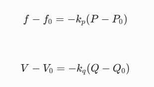
This mathematical mechanism based on droop control enables the energy storage cabinet to automatically achieve zero-steady-state-error adjustments of frequency and voltage—without requiring any external communication—during sudden local load increases or multi-unit parallel operation, thereby ensuring the self-healing and stable operation of the AC power network.
Industry Compliance and Standards Alignment: Aligning Control Timing with Major International Standards
When introducing our 100kW/215kWh C&I energy storage system to the global market, designing optimal pre-charge and black-start sequences is essential not only for system operation but also for meeting rigorous international certification requirements.
Compliance with IEEE 1547 and UL 1741 imposes strict limits on transient timing during grid-tied/off-grid transitions. To ensure the uninterrupted operation of critical loads within a microgrid, system-level dynamic switching responses—encompassing state detection, relay disconnection, and grid-forming algorithm activation—must typically be compressed to 10–20 ms or less (achieving UPS-level performance). This necessitates precise accounting for communication latency and the mechanical actuation time (including contact bounce) of physical contactors when optimizing BMS and PCS timing sequences.
Furthermore, the North American fire safety standard NFPA 855 mandates critical requirements for Emergency Shutdown (ESD) response timing. Upon detecting conditions such as individual battery cell thermal runaway, combustible gas leakage, or a short circuit, the BMS must unconditionally disconnect the main DC contactor via a hardwired circuit within milliseconds (typically <10 ms). This safety shutdown command overrides and bypasses any ongoing pre-charge, self-start, or state-machine transition processes, forcing an immediate shift to the `SYS_STATE_FAULT_SHUTDOWN` state to avert a catastrophic event.
Ultimately, overall dynamic switching performance and safety interlocks must undergo rigorous testing and validation within the framework of IEC 62933, the system-level standard for electrochemical energy storage. Only by tightly integrating physical safety, electrical transient analysis, and software-based timing control can the energy storage system successfully enter the global market.
Conclusion: The Perfect Coupling of Physical Constraints and Adaptive Control
The key takeaway from this commissioning case—involving the black start and on/off-grid transition of a 100kW/215kWh commercial and industrial battery energy storage system (BESS)—is that the system's control algorithms must never operate in isolation from underlying physical constraints.
Whether it involves the rigorous physical calculation of pulsed Joule heating (E=1/2CV^2) in the DC-side pre-charge circuit, or the seamless transition on the AC side from a grid-following (GFL) mode reliant on phase-locked loops (PLL) to a grid-forming (GFM) mode based on droop control, every microsecond-level control sequence must be anchored in the physical limits of electrical components and linked by adaptive, closed-loop state machines.
Only by abandoning the empiricism of blind "open-loop timing" in favor of a refined control chain based on physical models and adaptive feedback—and by embedding international compliance standards such as IEEE 1547, UL 1741, and NFPA 855 into the underlying logic from the design phase—can a BESS operate reliably during the rigorous "acid test" of a black start involving high-voltage transients.
Frequently Asked Questions (FAQ)
Q1: In a precharge circuit, what are the consequences of selecting a precharge resistor value that is either too low or too high?
A: This is a classic design trade-off issue. If the resistance is too low: while it significantly shortens the precharge time (reducing the time constant τ = RC), it results in an excessive initial transient inrush current (I_initial = V_bat / R) at the moment of precharging. This can easily cause dielectric breakdown or burn out the contacts of the precharge relay. If the resistance is too high: while it effectively limits the initial current, it results in an excessively long precharge time constant (τ). This not only slows down the system's startup response time (failing to meet the timing requirements for rapid grid-tied/off-grid switching) but also frequently triggers the BMS precharge timeout protection (set to 3.0 seconds in this case), causing the system to halt with error messages due to "incomplete precharge." Therefore, the resistance value must be determined through precise calculations that balance the DC bus capacitance (C) against the safe precharge time window.
Q2: Why does this design employ a "close main negative contactor first, then main positive contactor" sequence when closing the main contactors?
A: This approach is primarily driven by considerations regarding system-level safety and the reduction of electrical stress on the relays. In high-voltage systems (BDU), the precharge circuit is typically connected in series with the DC positive terminal (or on a dedicated precharge branch). Closing the negative contactor first establishes an equipotential reference between one side of the system (the negative terminal) and the PCS negative DC bus; since the main circuit remains open at this stage, no current flows. Subsequently, the system is precharged via the positive terminal (precharge branch) until the bus capacitance reaches a potential roughly equal to that of the battery, at which point the main positive contactor is closed. This strategy confines any arcing and associated contact damage at the moment of closure entirely to the last contactor to close (the main positive contactor), facilitating centralized lifespan monitoring and safety maintenance. It also ensures that, when the system is not in operation, both the high-voltage positive and negative terminals remain fully isolated from external circuits (dual isolation).
Q3: How can "phase discontinuity" (or "phase tearing") in AC-side voltage and current be avoided when switching from Grid-Following (GFL) control—based on a Phase-Locked Loop (PLL)—to Grid-Forming (GFM) control—based on droop control?
Answer: This represents a core control algorithm challenge in achieving seamless transfer between grid-connected and off-grid modes. If a phase discrepancy exists at the moment of switching between the virtual internal EMF phase output by the PCS inverter bridge and the phase of the residual voltage on the AC bus, a massive circulating current is generated, causing the converter to trip instantly due to overcurrent. Industrial-grade solutions address this during the transition period by employing "PLL Lock Freeze" and "Virtual Damper" techniques within the PCS control algorithm. At the microsecond moment the grid-connection contactor opens, the software captures the final locked angle of the PLL and uses it as the initial phase for the droop control integrator; simultaneously, a virtual impedance algorithm is utilized to absorb reactive circulating currents caused by transient voltage differences, thereby ensuring a smooth transition of the voltage vector and preventing "phase discontinuity."
Q4: Is there a secondary safety risk of the pre-charge resistor overheating and burning out following an Emergency Shutdown (ESD) triggered in compliance with NFPA 855 standards?
Author's Answer: Yes, there is. If an ESD is triggered suddenly during the pre-charge process (e.g., due to a sudden thermal runaway alarm in the battery), the BMS control system must ensure that the first step is to immediately cut off the drive power to both the pre-charge relay and the main contactor. If flaws in the hardware or software design result in only the main contactor opening during the ESD event—while the pre-charge relay remains closed due to a control failure or contact welding—the battery's high voltage will continue to discharge through the pre-charge resistor into the fault or short-circuit point. Since the pre-charge resistor cannot withstand the sustained short-circuit power from the battery cluster, it will rapidly generate intense heat within tens of seconds, potentially becoming a secondary ignition source that sets fire to surrounding components. Therefore, a safety design compliant with NFPA 855 must employ a hardwired interlock; specifically, the ESD signal must directly cut off power to the coils of all relays within the high-voltage enclosure (including the pre-charge relay) via a physical circuit—bypassing software MCU processing—thereby achieving an absolute physical disconnection.
How to Protect Residential Batteries During Extreme Heatwaves? A Comprehensive Guide to Thermal Safety and Overheat Prevention
U CRA Compliance Guide: How to Choose a Hybrid Inverter for C&I Solar


contact us
For more questions please


Office Address: 701, Building A, Yonghuayuan Business Building, Baotian 2nd Road, Chentian Community, Xixiang Street, Bao'an District, Shenzhen, Guangdong Province, China
Factory Address 1: Room 701, Building 2, Kegu Industrial Park, Zone B, Jian'an Road, No. 790, Chang'an Town, Dongguan City, Guangdong Province, China
Factory Address 2: Building 7, Phase II Standardized Factory, Innovation Industrial Park, Duji Economic Development Zone, Huaibei City, Anhui Province, China